 | FWF Misc Log |
|
|
| ||||||
|
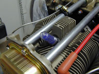
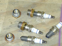
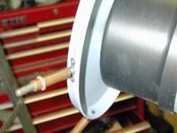
Home Project News February 3, 2021 Project Log Empennage Horizontal Stabilizer Vertical Stabilizer Rudder Elevators Rudder II Wing Kit Wings Fuel Tanks Ailerons Flaps Fuselage Kit Bulkheads Aft Section Foreward Section Top Fuselage Cabin Finish Canopy Cowling Electrical Firewall Forward Fuel System Engine Baffles Misc Miscellaneous Fiberglass Assembly Panel Finishing Up! FAQ Project Notes Project Summary Guestbook Other Stuff | There are a bunch of details forward of the firewall that just don't have another category to be filed under so I put them here. Installed the deyhdrator plugs into the top spark plug holes. Punched the hole for the cabin heat box. I had to install the fuel injection servo temporarily so that I could locate the holes for the mixture and throttle cables to pass through the firewall. I punched those holes as well as the hole for the mixture cable.
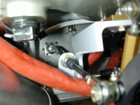
I drilled the holes for the cabin heat box to mount to the firewall. I have decided to use screws and nutplates instead of rivets since I may have to remove the box to get to the prop governor. I finished installing the little eyeball cable penetrations on the firewall for the throttle, mixtrure and prop control cables. I still need to put in two more. These were a little more trouble than I thought they would be but they look cool when finished.
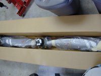
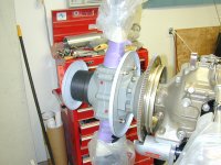
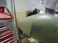
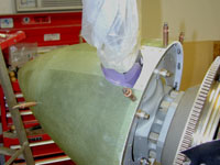
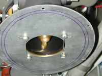
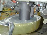
Took the Prop out of the box. It's a thing of beauty. I put it up on the work bench where I could get to it and started building the rear spinner bulkhead which is two parts riveted together but the hard part is cutting the strange shaped hole to fit around the prop.
Primed the spinner bulkhead parts, and riveted the rear spinner bulkhead together. Then I mounted the bulkheads on the prop and made a template to trim the cutouts on the spinner. I used the template to cut the spinner. It took some time but it came out okay. I still need to trim the cutouts a little bit more but for now I just wanted to make sure that I wouldn't have to space the bulkheads any to get it all to work. When all that was done I mounted the prop to the engine. It is possible to do this alone but I won't do it again.
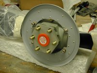
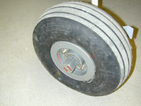
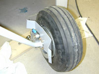
I still hadn't ever gotten around to finishing the brake installation on the main gear. So I spent some time tonight getting all the parts made and putting the rest of the main gear parts together. Drilled holes in the axles for the cotter pins, and installed the brake calipers.
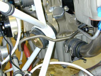
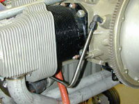
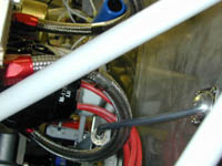
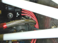
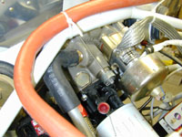
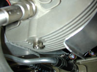
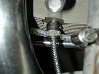
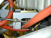
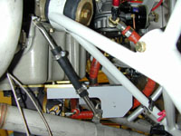
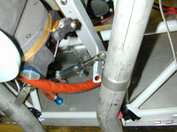
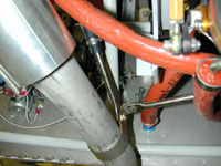
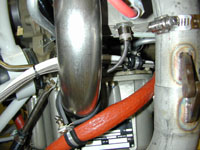
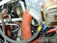
I spent some time fiddling with some firewall forward stuff. I am not happy with where I mounted the capacitor for the SD-8 alternator because the wiring get's in the way of removing the battery. I'll either move the capacitor or change the wiring somehow. I also moved the ground strap to the engine since it also made it impossible to remove the battery. I made a bracket for the purge valve control line that attaches to one of the engine case bolts. Don came over tonight and made me a beautiful prop governor oil line. The engine came with a hose that was WAY too long (It looks like was probably for an O-540), and I never liked the hose idea anyway. So since Don is one of the best instrument hands on the planet I traded him some BBQ for his skills. I am very happy with it. It's made out of 316SS 3/8x0.035 seamless tubing.
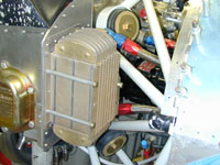
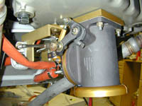
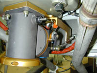
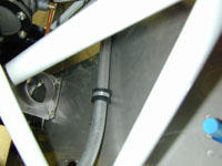
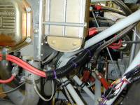
Finished the hose that connects the AFP purge valve to the firewall bulkhead. I also managed to get the oil cooler installed.
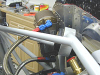
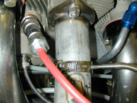
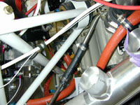
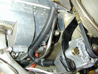
I need to get the firewall arrangement sorted out so I started installing as much of that stuff as I can. I figure that the wiring will be the easiest to route around stuff so I want the controls and hoses to be installed before I get too carried away with wiring. I spent today installing the fuel servo and the throttle, prop and mixture controls. The throttle control I bought requires a smaller hole than what I had drilled so I had to make another mounting plate, then I ran the prop control to the governor since this was the one that really had me worried since it runs right past the oil cooler hoses and the spark plug wires on the left mag. The prop cable fits like a glove but when I put the throttle and mixture cables in I realized that they were probably too long. I'll play with them later to see if I can make them fit better but I may re-order them.
I made the little bracket to mount the mixture cable to the fuel servo. Rerouted the mixture and throttle controls to try and get them to fit better. Ran the control cable for the AFP purge valve. I can't believe it took me 3 hours to install a few nutplates but these things are a pain when they are on the firewall. I managed to get the nutplates for the inside cover, the oil pressure line and the crankcase vent line drilled I got most of them installed and I noticed that I had used nuts to install the sender manifold. That will never do, so I put some nutplates there too. I also put the pipe fittings in the sender manifold for the oil pressure and fuel pressure. I almost got it installed again when I realized that I had installed the wrong nutplate on one of them. One day I'll learn to go to bed when I get tired.
Replaced that nutplate behind the sender manifold, mounted the manifold and attached the hoses.
I pulled the exhaust and drilled the holes for the EGT probes. I installed the bayonet fittings for the CHT probes and then installed the the exhaust, EGT prbes and CHT probes. I also put the oil temperature sensor in oil filter adapter.
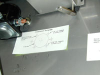
Started work on the spinner. The first step was to get the spark plugs out of the engine so I could turn it over safely. Then turning the prop over and over to check that the spinner turns true, with no wobble.
I sanded on the cowling a little bit. Also did some more work on the spinner. Still trying to get it lined up just perfect. I have had to sand a little bit of the inside. More work on the spinner. Made the gap covers for the spinner and finished up all the drilling and riveting of the nutplates on the spinner. There are 22 screws holding that thing on. That is a lot of holes. The spinner is finished except for paint.
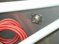
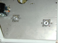
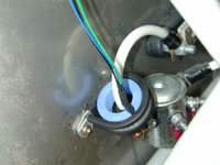
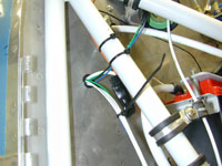
I finished mounting the the current sensors. Cut a hole and installed a snap bushing for the wires to go through the firewall on the right side of the plane. I piddled around with some of the smaller wires on the contactors. I also worked on the control cable brackets.
Finished and remounted the control cable mounts. Installed the exhaust mounts, and while I was at it I put the cabin heat muff on. I had forgotten about the cabin heat muff and had an interference issue that I had to work out. Those exhaust mounts were far more difficult that I thought they would be and I advise everybody to do it earlier in the process than I did.
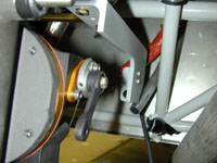
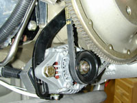
I had to cut the adjustment arm down on the alternator. This is the long arm with the curved slot in it that allows you to adjust the belt tension. It was too long and with the correct belt installed I couldn't get the bolt in, so I drilled another hole in it on the end that mounts to the engine and cut the old hole off. I went ahead and mounted the alternator and then spent some time tidying up some of the wires on the engine. I also started working on the alternator blast tube.
Finished the alternator blast tube.
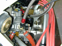
I spent a little time today finishing up a few details that I wanted to get done and couldn't until the panel was in. I made the new throttle and mixture cable brackets. The old ones were made from 062 angle and I wasn't sure they'd stand up to the vibration. I replaced them with 0.125 angle. I also fixed the cabin heat muff. It was loose on the exhaust after tightening the hose clamps all the way. Then I mounted the throttle/prop/mixture/purge controls under the instruent panel and ran the cables through the firewall. I wanted to have those installed before getting too carried away on wiring. Wires are easy to route around control cables but control cables aren't so easy to route around wires.
Connected the Mixture, Governor and Purge control cables to the AFP and prop governor. Reinstalled the fuel tank vents (hopefully this will be the last time). I also started scratching my head trying to figure out the best way to get the cabin heat control cable through the firewall without interfering with too much stuff. The jury is still out. I couldn't bring myself to do any wiring today so I piddled around 'under the hood' I reset my mixture cable according to info that I got from AFP. I don't quite have enough travel to move the mixture arm. I am talking just a little bit too short like 1/32". I had it where I got ICO but not full rich. AFP said do the opposite since I'll be killing the engine with the purge valve. I also installed the fuel pump drain line.
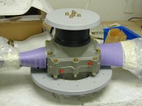
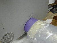
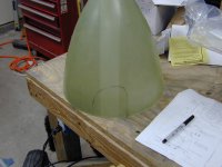
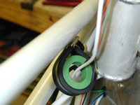
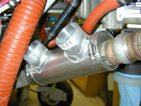
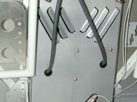
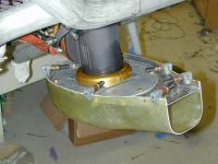
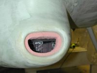
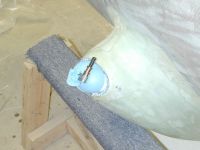
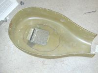
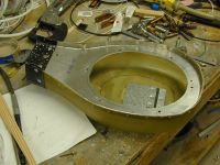
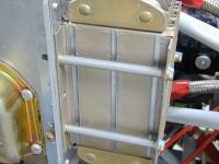
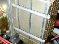
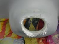
Ran the cabin heat cable through the firewall and hooked it up. I also started putting those stainless firewall penetration sheilds around the grommets where the cabin heat cable and the purge valve cable come through the firewall. Started fitting the filtered air box to the engine. I started by fluting the flanges of the mouting plate and getting the sleeve that is on the AFP turned so that the inlet lines up with the opening in the cowling. I finished getting the neck of the FAB lined up with the cowling. It took some pretty sharp flutes to get the top plate to bend enough. Then I spent a long time shaping and forming the foam block that is used to form the inlet transition. After all that it only took a few minutes to layup the glass on the foam.
Trimmed and sanded on the inlet duct for the air box. I think I am going to have to cut part of it and re do it but we'll see once I get it trimmed back to the right length.
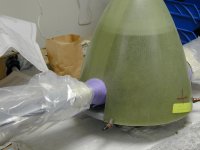
Trimmed and sanded on the inlet duct some more. Apparently I didn't get the cloth layed down very well on the left bottom so I cut that out, did the foam thing and re-layed some glass on it. Sanded the inlet duct some more since I had to do that layup to fix it. I took the filter box off and started cutting and drilling the holes for the alternate air door. Finished the alternate air door in the air filter box.
Finsished the air filter box.
I didn't like the cheesy little tab washers that came in the FAB kit for mounting the airbox mount plate to the AFP servo. I had some drilled cap-screws that were the right diameter and pitch but they were too long. So I cut them down to size and instlled them. Then I safety wired them. I really don't want anything to come loose in there and get sucked into the engine.
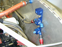
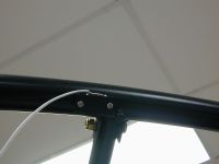
Today I worked on a bunch of little details. I installed a little switch for the canopy latch warning light. I worked on the new fuel selector plate (I was never happy with the old one.) I replaced all the nylok nuts that I had in the engine compartment. I also put the washers on each end of the tubes on the oil cooler. It seems that having the raw aluminum tubing against the oil cooler flanges is causing some pre-mature failure. The fix is to shorten the tubes and install some washers between them and the flanges.
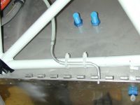
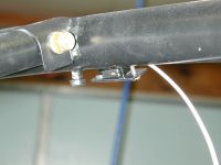
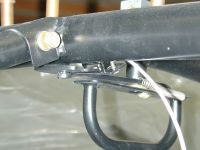
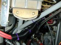
Made up some brackets for holding the top spark plug wires. Actually all I did was secure the right side ones to the fuel return hose and the left side I screwed it to the cross brace for the baffles. I been struggling with exactly how I wanted to support the spark plug wires leading back to the Mag. I decided to use some of that nylon corrugated tubing that is split down the side to put the plug wires in and then support that.
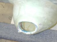
Filled and attempted to bleed the brakes. I have them pretty well bled but there is a little air in them that still needs to come out. My problem was the silly little pump that I used to fill the system. The idea is to use some kind of pump to fill the brakes from the bottom up but I think the one that I used was putting air in the line. I'll try again with a better pump. I started fixing the filtered air inlet. I installed the split ring on the AFP fuel controller upside down and that moved the whole thing down a half inch. Now it's right so I have to cut the inlet duct off and re-fiberglass it.
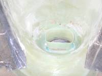
I glassed the new inlet duct for the FAB.
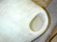
I put another couple of layers of glass on the inlet duct. I sanded off the foam and then put two more layers around the two layers that I put on yesterday.
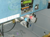
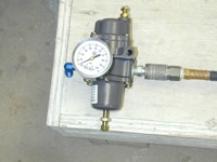
Trimmed and sanded the new induction air inlet on the cowling. I added some filler to get it all nice and smooth. There is still some sanding in my future. I borrowed a regulator and a gauge from work this weeked to check my Oil and Fuel pressure senders. I assembled a small test right with it and used shop air to test them. They both worked perfectly. I also boiled some water and checked my oil temperature transducer.
|