 | Electrical Log |
|
|
| ||||||
|
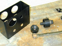
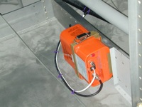
Home Project News February 3, 2021 Project Log Empennage Horizontal Stabilizer Vertical Stabilizer Rudder Elevators Rudder II Wing Kit Wings Fuel Tanks Ailerons Flaps Fuselage Kit Bulkheads Aft Section Foreward Section Top Fuselage Cabin Finish Canopy Cowling Electrical Firewall Forward Fuel System Engine Baffles Misc Miscellaneous Fiberglass Assembly Panel Finishing Up! FAQ Project Notes Project Summary Guestbook Other Stuff | The canopy frame was about to drive me nuts so I decided to start building my battery box. I got the parts out and marked the center of the lightening holes. I finally remembered to borrow the 2" Greenlee punch from work so I worked a little more on the battery box. The 2" punch is for the lightening holes. The circle cutter was just not gonna work on the steel, but the punch worked really well.
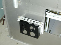
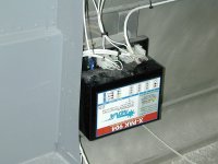
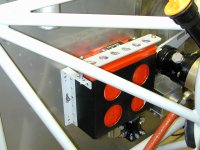
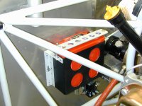
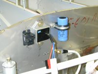
Finished the battery box and started installing the nutplates and doubler plates on the firewall for mounting the battery and starter contactors.
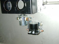
Finished mounting the contactors and made the copper bar that connects the two together.
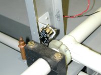
Installed the flap position switch for the PSS Angle of Attack indicator.
Removed the roll bar and the roll bar brace and repainted them. They had gotten beat up a little bit during the construction phase. I also ran the wires from the strobe power supply. This was one of the items on my to do when there's nothing else to do list and since I was waiting for help on the canopy I decided to do the strobe wires.
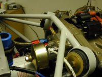
I got a few toys from the mailman today and one of them was my Odessey battery, so I installed it. I also piddled with the alternator a little bit.
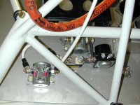
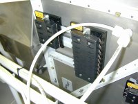
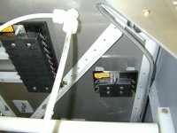
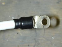
Mounted the starter and worked on some of the big wires. Mounted the ground block and started trying to find a place to put the fuse blocks. I started building some stand offs for the fuse blocks because I'm going to mount them on the firewall but I don't want all those nutplates on the engine side of the firewall. I'll rivet the standoffs onto the firewall (flush side forward) and mount the fuseblocks to the stand offs. I finished fabricating the stand offs for the fuse blocks. I also mounted the ANL current limiter base and figured out where I am going to put the alternator contactor, and made the doubler plate to mount it. Mounted the fuse blocks and the alternator contactor. I had to remove the battery box to rivet the stand offs for the fuse blocks. I started making the big cables.
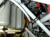
Worked on big wires. Finished the Alternator wire. Mounted and connected the diode between the Main Buss and the Essential Buss. Made the ground wire for the battery to firewall connection. I also mounted the SD-8 backup alternator to the vacuum pump pad on the engine.
Made the 4AWG cable for the main buss connection and passed it through the firewall with a rubber grommet and a stainless cover. Passed the battery buss feed through the firewall. I also mounted all the components for the SD-8 backup alternator.
Worked on the wiring a little more. I got most of the SD-8 alternator wiring done. Put in the small wire that goes to the alternator and spent some time securing wire with Adel clamps. Finished the starter cable, and played around a little with how I am going to run the wires through the little tunnel in the center of the floor.
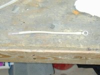
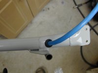
I drilled a hole at the bottom of the pilot's control stick for a grommet to pass the wires through from the stick grip.
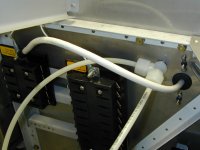
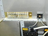
Worked on mounting the Hall Effect current sensors and re mounted the capacitor for the SD-8 alternator. Replaced my 10 slot main buss fuse block with a 20 slot version. 10 was going to work but it was going to leave me with no spares, so I now have a 20 slot fuse block for both the e-buss and the main buss. Hooked up the starter circuit and Main alternator circuit. Wired up the Aux alternator and the fuel pump. Worked on wiring the trim There are more wires in these two little trim systems than I thought. I spent the evening running wires from the aileron servo to the controller and from indicators to the controller.
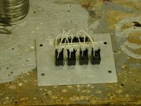
More trim wiring. Finished up the trim wiring and finished soldering the connector on my little home grown annunciator. Worked on a little wiring. I connected a few more points to my annunciator panel. Hooked up the wires to the GPS connector. Since I can't install the GPS until the forward top skin is on I put the wires in a Mate-n-lok connector. Soldered together my little voltage regulator and tested to make sure it would work. This voltage regulator is for the lamp in the autopilot and the comm radio.
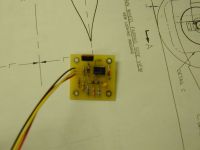
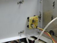
Installed and wired the Low Voltage Monitors. I made these circuits from a schematic that Bob Knuckles sent me. I also wired the small inverter that will eventually power the E.L. light that I plan to put under the glaresheild.
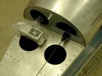
Installed the ELT behind the baggage compartment on the lower rib that the elevator bellcrank is mounted on. I put the antenna under the emp fairing.
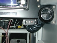
It took entirely too long for me to run that wire for the ELT but I finally got the little remote installed on the right side of the panel.
|