 | Engine Log |
|
|
| ||||||
|
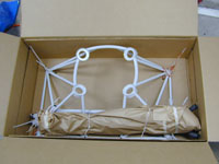
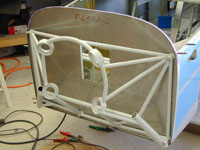
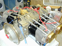
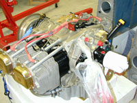
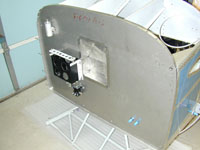
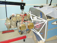
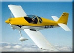
Home Project News February 3, 2021 Project Log Empennage Horizontal Stabilizer Vertical Stabilizer Rudder Elevators Rudder II Wing Kit Wings Fuel Tanks Ailerons Flaps Fuselage Kit Bulkheads Aft Section Foreward Section Top Fuselage Cabin Finish Canopy Cowling Electrical Firewall Forward Fuel System Engine Baffles Misc Miscellaneous Fiberglass Assembly Panel Finishing Up! FAQ Project Notes Project Summary Guestbook Other Stuff | The engine in my plane is a Superior Air Parts XP-360-B1A2 with an Airflow Performance Fuel Injection system and one Lightspeed Plasma II+ CD Ignition system in place of the right mag. Did a pretty major cleanup of the garage, and drilled the holes for the engine mount.
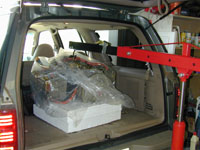
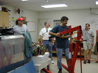
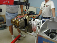
Steve came over and helped me unload the engine.
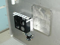
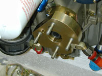
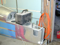
Drilled some lightening holes in the center rudder pedal brace and riveted it to the firewall. Riveted in the firewall recess with a little Pro-seal. Mounted the battery box to the firewall. Installed the engine mount but I didn't get the bolts tight, I'll need some help on that one. I also tried to get the governor installed on the engine but I am not quite sure that I have the right studs. I'll check with the mailing lists tomorrow and see what gives.
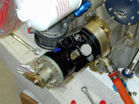
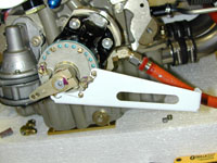
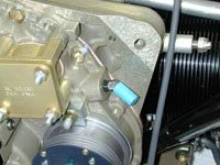
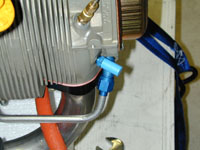
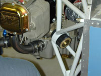
Trying to get ready to hang the engine. I mounted the prop governor, and the governor control bracket. It isn't going to work like that because the the control cable will have to run through my battery. I don't really want to drill a hole in my battery so I need to figure out how to fix it. I installed the fittings for oil pressure, manifold pressure, fuel pressure and the oil cooler lines in the back of the engine.
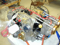
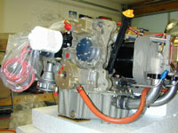
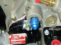
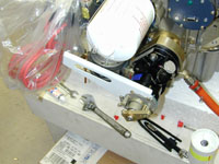
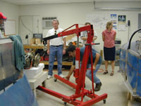
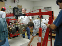
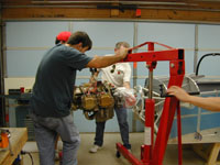
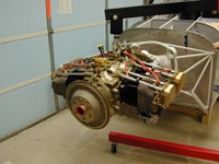
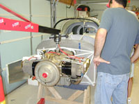
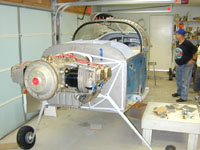
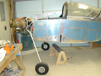
I figured that I would try to rotate the plate on the back of the prop governor to and it worked. I put the remote sender manifold on the firewall. Everybody started showing up for the engine hanging party and after some RV talk and hamburgers we managed to get the engine on the mount. It went really smooth and only took about a half hour. After the engine was on everybody that showed up decided that they didn't like my sawhorse under the fuselage idea and we decided to put it up on the gear. I hadn't put the wheels or anything together yet so we had to do all that. With all the people that were there it only took a couple of hours, but we didn't do the brakes or the wheel pant mounting hardware. We just did enough to get the wheels on. Thanks everybody that came over to help. Marshall, Steve, Charles, Clay, David and Darin all helped. I also have to thank my wife, Shannon, for the burgers and cake, it was a lot of fun.
Covered all the holes in the engine and made sure all the open fittings had covers. Put all the cotter pins in the engine mount, and while I was at it I put some cotter pins in the rudder pedals where I had run out earlier and since I was in the cabin anyway I went ahead and tightened up all the rudder pedal hardware. Spent some time sorting through drawings and cleaning the place up it was getting to be a real mess. |